Chapter 1: System Components
Architecture, component inventory, functions, and key performance indicators for all subsystems
1.1 System Architecture
The underground parking surveillance system is structured as a multi-tier architecture that connects field devices through a converged IP network to a centralized management and recording platform. The architecture is designed for scalability, redundancy, and clear separation of concerns: each layer has defined responsibilities, and all inter-layer communication follows documented protocols and data flows.
Camera groups are organized by functional zone — entrance LPR, ramps, aisles, intersections, bay areas, elevator lobbies, guard booths, and equipment rooms. Each zone connects to a dedicated PoE access switch housed in a local distribution cabinet. Access switches uplink via fiber to floor-level distribution switches, which in turn connect to a dual-stack core switch in the main equipment room. The core switch serves as the convergence point for all video traffic, platform services, and integration interfaces.
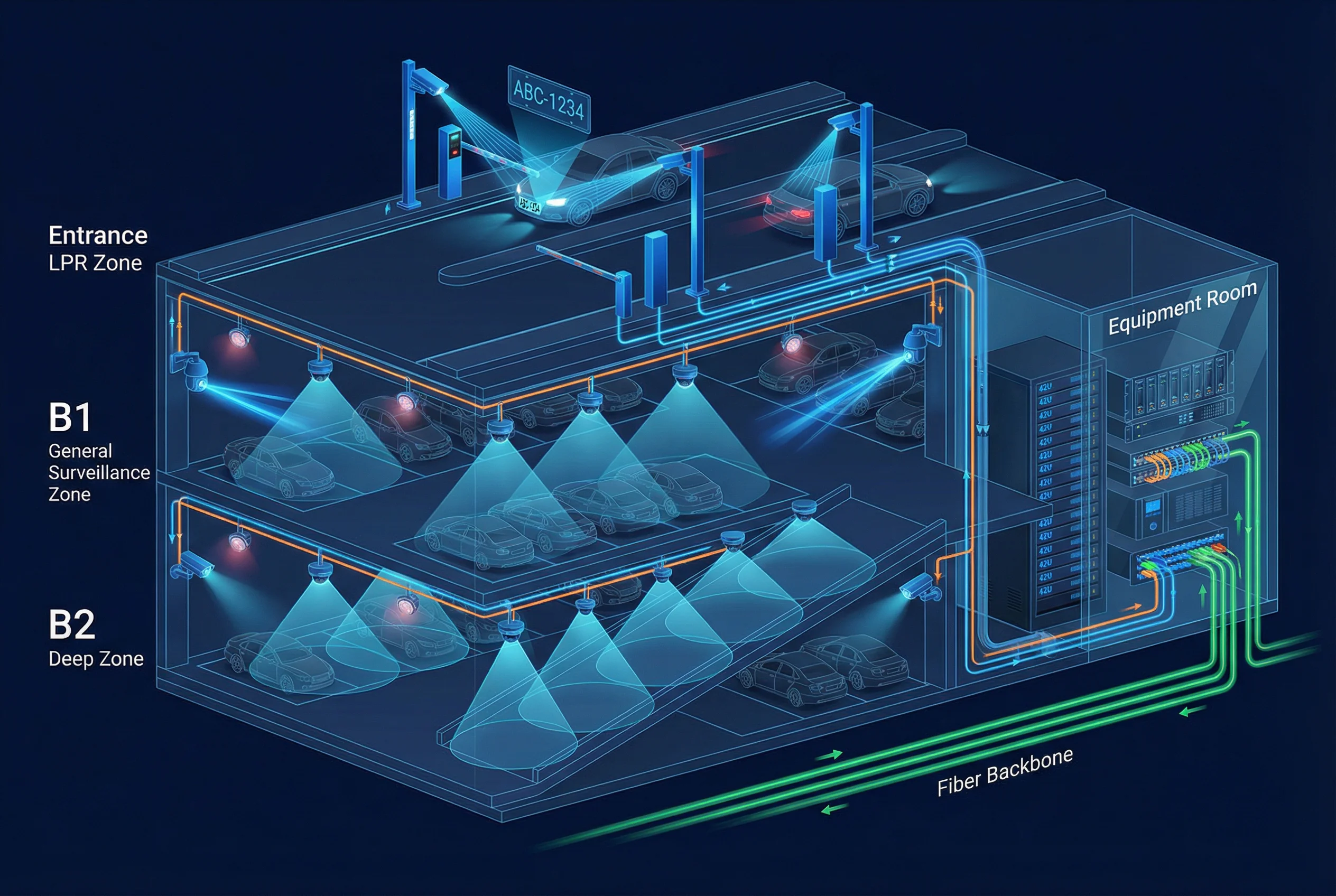
Figure 1.1: System Component Relationship Diagram — Camera Groups, Switching Layers, Platform Servers, Clients, and External Systems
Core Modules
- Cameras: Fixed box/bullet, turret, dome, fisheye/multi-sensor, and dedicated LPR cameras — selected per zone requirements
- PoE Access Switches: 24/48-port managed switches with fiber uplinks, VLAN tagging, and port-level monitoring
- Distribution / Core Switching: L3 routing, QoS prioritization, redundancy via MLAG or stacking, and multicast control
- VMS and Recording: Video Management System with NVR or dedicated storage array; supports ONVIF and vendor SDK
- Time Synchronization: NTP server (GPS-disciplined or stratum-2) with monitoring; mandatory for all devices
- Client Terminals: Control room video wall, operator consoles, and mobile clients for remote access via VPN
- Monitoring and Alerting: SNMP/syslog collection, VMS health dashboard, and automated ticketing integration
Optional Modules
- LPR/ANPR Engine: Edge-based (camera-embedded) or server-based license plate recognition with black/white list management
- AI Analytics: Loitering detection, wrong-way vehicle alerts, pedestrian intrusion, and fall detection in stair areas
- Parking Guidance Integration: Bay occupancy data fed to guidance signs via VMS or dedicated occupancy sensors
- Evidence Integrity Services: Cryptographic hashing, watermarking, and immutable storage tier for legal-grade evidence
Supporting Modules (Must Be Planned)
- UPS, PDUs, surge protection devices (SPD), and equipotential grounding
- Cabinets and enclosures with ventilation, dehumidification, and temperature monitoring
- Structured cabling system with consistent labeling (camera ID → port → switch → cabinet)
- Fire linkage I/O interfaces and documented safe-shutdown rules for fire mode
| Layer | Key Flows | Protocol / Interface | Redundancy Requirement |
|---|---|---|---|
| Field → Access | Video stream + PoE power | RTSP/ONVIF over Cat6, 802.3af/at/bt | Dual power feed to access switch |
| Access → Distribution | Aggregated video + management | 10G fiber, LACP bonding | Dual fiber uplinks (A/B paths) |
| Distribution → Core | Inter-floor routing + QoS | 10G/25G fiber, OSPF/static | MLAG or dual-homed uplinks |
| Core → Platform | Recording ingest + management | 10G iSCSI/NFS or direct attach | HA server pair, RAID6/10 storage |
| Platform → Integration | Events, plate data, alarms | HTTPS REST API, MQTT, dry contact | Retry logic, message queue |
| Time Sync | NTP to all devices | NTPv4, stratum hierarchy | Dual NTP sources, monitoring |
1.2 Components and Functions
Each component category in the system has specific functional roles, measurable key performance indicators, and known mismatch risks when specifications are not met. The following matrix provides a comprehensive inventory of all major component types, their critical parameters, primary functions, and acceptance KPIs. Selecting components below the minimum specifications creates predictable failure chains — for example, insufficient WDR results in unreadable plates at entrances, while undersized PoE budgets cause camera reboot loops that create recording gaps.

Figure 1.2: System Component Inventory Matrix — Categories, Key Parameters, Functions, and Acceptance KPIs
| Component | Key Parameters | Primary Function | KPI / Acceptance | Mismatch Risk |
|---|---|---|---|---|
| LPR Camera | WDR ≥120dB; shutter 1/2000–1/5000; 2MP+; IR/white light | License plate capture at entrances and exits | Read rate >95%; misread <0.5% | Plate washout under headlights; billing disputes |
| Dome / Turret Camera | WDR ≥100dB; 2–4MP; IP66/67; IK10; PoE af/at | Aisle, lobby, ramp, and bay area coverage | No blind spot >2m; stable 25fps | Fogged lens; vandalism; motion blur |
| Fisheye / Multi-sensor | 4–12MP; 180°/360° dewarping; PoE bt ≤60W | Bay area overview; intersection panoramic coverage | Full bay visibility; dewarped clarity | Distortion artifacts; insufficient resolution at edges |
| PoE Access Switch | PoE budget 370–740W; 10G uplink; LACP; VLAN | PoE power delivery + data aggregation per zone | Port utilization <80%; PoE headroom ≥25% | Overload → reboot loops → recording gaps |
| Distribution Switch | L3; 10G SFP+; OSPF; QoS; storm control | Inter-floor routing; redundancy (MLAG) | Failover <50ms; zero packet loss | Congestion → evidence gaps; no redundancy |
| NVR / Storage | RAID6/10; hot spare; write ≥1.5× total bitrate | Continuous recording; 30–90 day retention | No recording gaps; playback start <2s | Disk failure → data loss; undersized → overflow |
| VMS Server | Camera license count; HA pair; API/SDK support | Management, search, evidence export | Retrieve clip <3 min; hash verification pass | License limit → cameras unmanaged; no HA → downtime |
| UPS | Runtime 30–60 min (core); 15–30 min (edge) | Power continuity; graceful shutdown | Power cut test pass; no DB corruption | Abrupt shutdown corrupts recording index |
| NTP Server | Accuracy <1ms LAN; redundant sources | Time synchronization for forensic correlation | All devices <500ms offset from NTP | Time drift → multi-camera replay unusable |
| Illuminator | IR 850/940nm or white light; adjustable power | Supplement illumination in dark zones | Uniform coverage; no hot spots; no glare | Overexposure; reflections from wet surfaces |