Chapter 11: Installation & Debugging
Pre-installation requirements, installation procedures, construction norms, and systematic debugging methods
11.1 Pre-Installation Requirements
Pre-installation verification is the most cost-effective quality control activity in the entire project. Every problem identified during a pre-installation walkthrough costs a fraction of what it costs to fix after cables are pulled and cameras are mounted. The following twelve checks must be completed and signed off before any installation work begins. Each check has a specific risk associated with skipping it — the risk is documented so that project managers can make an informed decision about which checks to prioritize when time is limited.
| # | Pre-Installation Check | Risk if Skipped | Verification Method |
|---|---|---|---|
| 1 | Confirm mounting surfaces, structural capacity, and camera heights at all positions | Camera installed at wrong height or on inadequate surface → rework required | Site walkthrough with drawings; structural check if needed |
| 2 | Confirm cable routes and fire-stopping requirements at all penetrations | Cable route blocked; fire penetration not sealed → regulatory non-compliance | Route walkthrough; confirm fire stopping material available |
| 3 | Verify power circuits, circuit breakers, and UPS are installed and energized | Cameras installed but no power → commissioning delayed | Electrical panel inspection; UPS status check |
| 4 | Verify grounding points and equipotential bonding bus are installed | Surge damage to PoE ports and cameras during first storm event | Continuity test from cabinet locations to ground bus |
| 5 | Verify cabinet locations are away from seepage and water ingress points | Water damage to switches and servers → total zone outage | Inspect ceiling and walls above cabinet locations; check drainage |
| 6 | Validate that fiber paths A and B are routed through physically separate conduits | Single cable cut disables both redundant paths → floor-level recording outage | Route drawing review; physical conduit inspection |
| 7 | Confirm IP address plan and VLAN assignments are finalized and documented | IP conflicts during commissioning → extended troubleshooting delays | Review IP plan document; confirm with network team |
| 8 | Prepare labeling scheme: zone + camera ID format agreed and printed labels ready | Inconsistent labels → miswiring during repair → extended outage | Review labeling standard; confirm label printer and materials available |
| 9 | Confirm tool availability: fiber power meter, cable tester, torque screwdriver, lux meter | Installation proceeds without proper testing → defects not detected until commissioning | Tool inventory check; calibration certificates current |
| 10 | Prepare consumables: cable glands (matched to cable OD), silicone sealant, desiccant packs | Installation halted waiting for consumables → schedule delay | Consumables inventory check against camera count |
| 11 | Verify access permissions to all areas including equipment rooms and parking levels | Installation team cannot access areas → schedule delay; security incident | Access card/key availability check; escort arrangement if needed |
| 12 | Risk walkthrough: entrances (headlight angles), ramps (blind apex), lobby (face angle), equipment rooms (EMI sources) | Camera positioned in suboptimal location → performance issues discovered after commissioning | Walkthrough with camera position drawings; simulate vehicle movement |
11.2 Installation Requirements
The following four installation scenarios represent the most critical and most commonly problematic installation types in underground parking surveillance systems. Each scenario has specific requirements that differ from standard indoor camera installation, and each has a documented set of common errors that must be actively avoided. The installation images below show correct installation practice for each scenario.
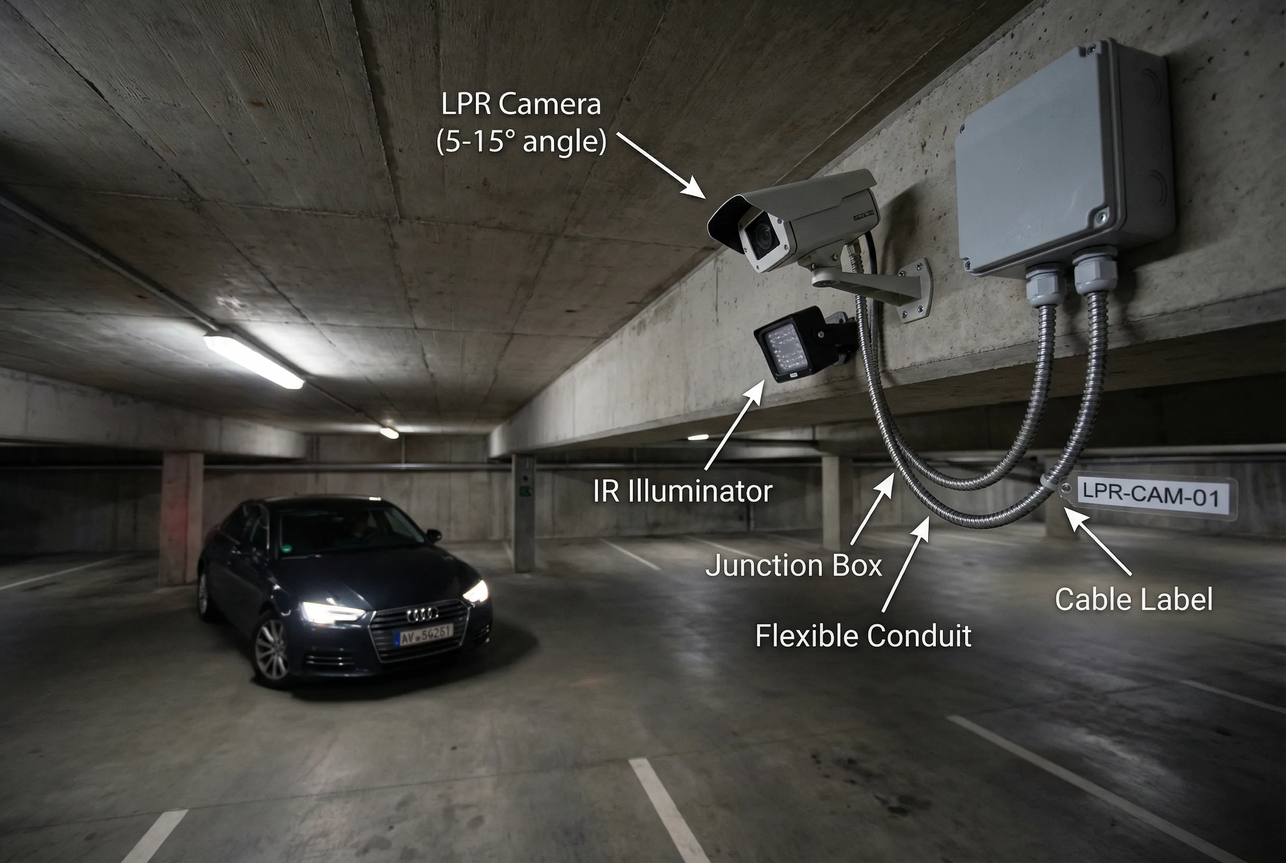
Scenario 1: Entrance LPR Camera Installation
The LPR camera is fixed to the side beam of the lane, with the optical axis at a small angle (5–15°) to the vehicle direction to avoid direct headlight glare. The IR supplemental illuminator is mounted below and to the side of the camera to reduce specular reflection from license plate surfaces. A sealed waterproof junction box with IP67 cable glands and metal flexible conduit protects all cable terminations.
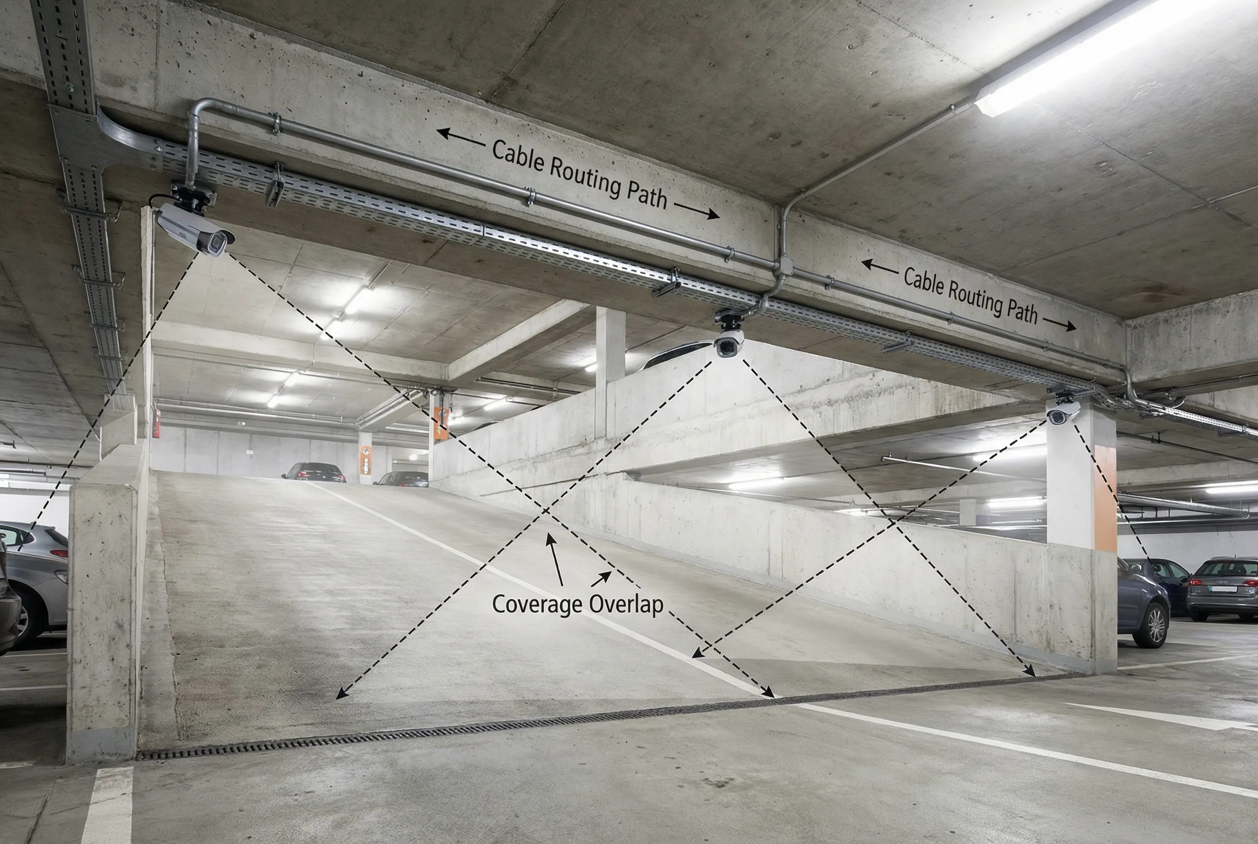
Scenario 2: Ramp Camera Chain Installation
Three cameras are installed at the ramp entrance, midpoint, and exit with overlapping coverage zones to eliminate blind spots at the apex of the ramp curve. Cables are routed in metal conduit fixed to the beam underside with anti-vibration cable clips. The overlapping coverage zones are shown as dashed lines, ensuring continuous tracking of vehicles through the ramp transition.
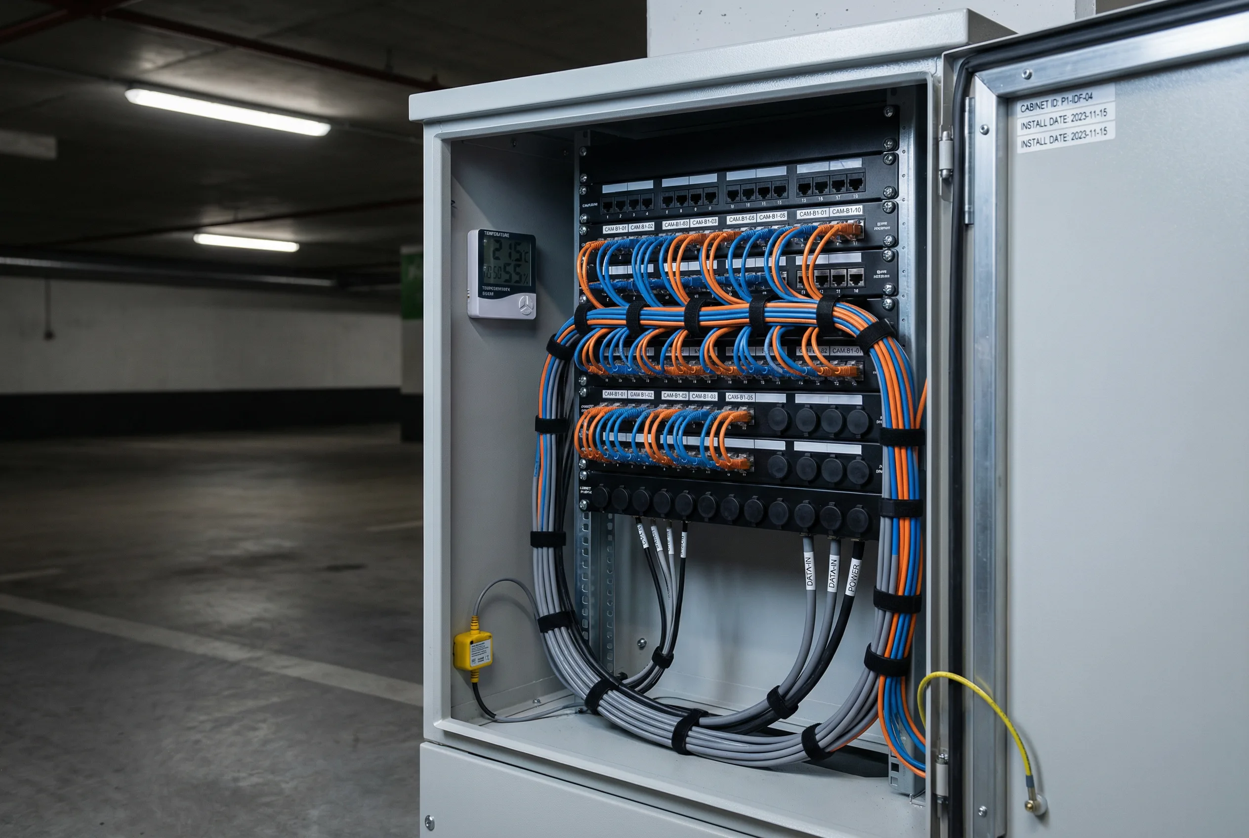
Scenario 3: Floor Distribution Cabinet
The floor-level distribution cabinet shows a neatly terminated patch panel with consistent jumper cable lengths and port labels matching camera position numbers. A temperature and humidity sensor is mounted inside the cabinet, and a water ingress sensor is installed at the base. All cables are bundled and labeled at both ends, and spare ports are covered to prevent dust ingress.
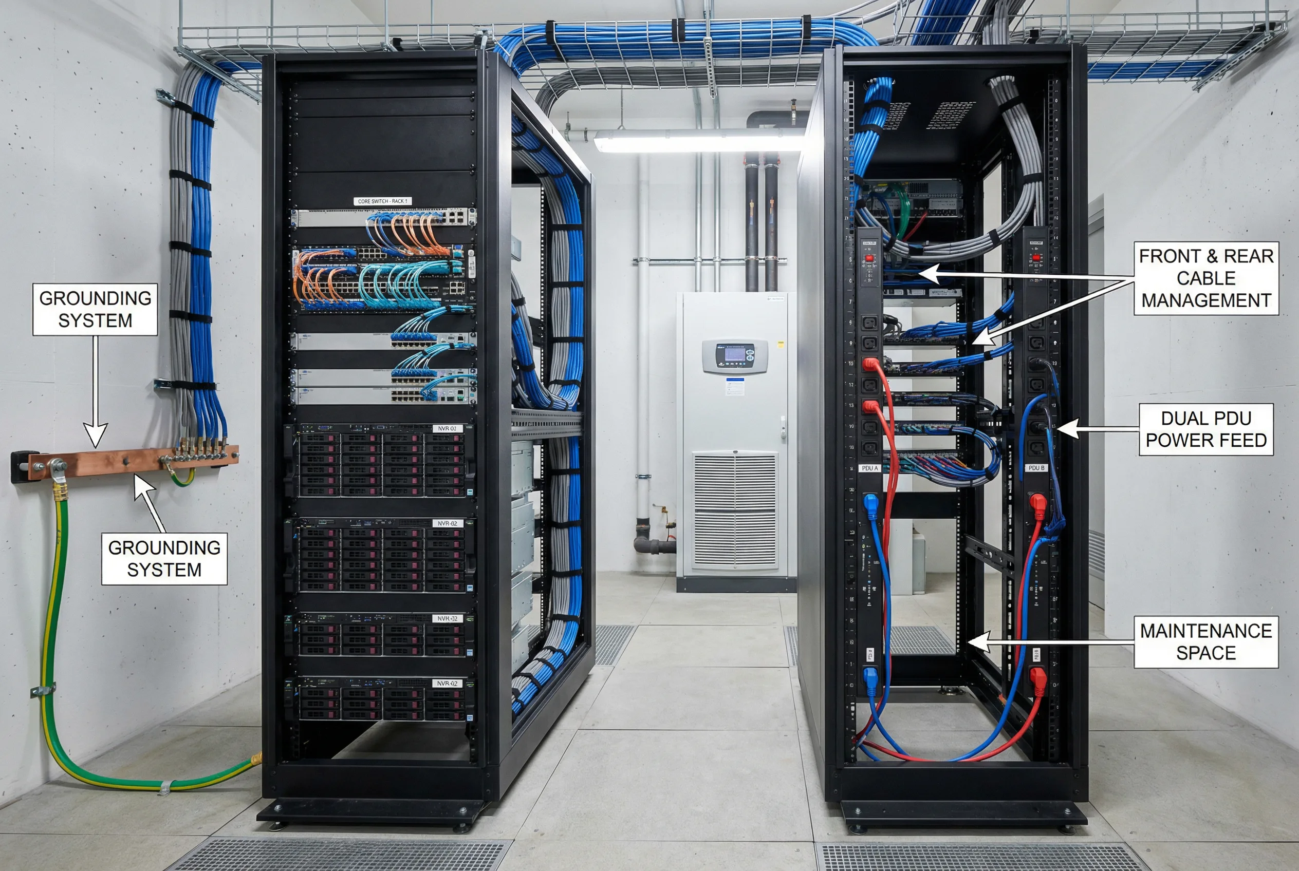
Scenario 4: Equipment Room Rack Installation
The equipment room rack shows core network switches and NVR servers installed in proper rack positions with front and rear cable management, adequate maintenance space between racks, and dual PDU power feeds (A and B paths). The grounding cable is connected to the ground bus bar, and all rack units are labeled with asset tags. The precision air conditioning unit is visible in the background.
Correct Installation Steps (Summary)
- Install mounting brackets and junction boxes at all camera positions; verify structural integrity.
- Route conduits from junction boxes to distribution cabinets; form drip loops at all camera entries.
- Pull cables through conduits; terminate at patch panels and camera junction boxes.
- Certify all copper runs to Cat6 standard; measure fiber insertion loss on all uplinks.
- Configure switches: VLAN assignments, PoE class, LACP uplink bonding, QoS DSCP marking.
- Mount cameras on brackets; apply waterproofing sealant; install desiccant packs.
- Configure camera profiles: resolution, bitrate, codec, exposure zone, WDR, IR mode.
- Enroll cameras to VMS; verify recording starts; verify storage write latency.
- Verify NTP synchronization on all cameras and VMS; confirm offset within ±1 second.
- Run lighting stress tests: headlights, night, mixed lighting; verify LPR performance.
Common Installation Errors
| # | Common Error | Consequence | Prevention |
|---|---|---|---|
| 1 | Camera mounted too high or at too steep a downward angle at entrance | License plate appears at extreme angle → unreadable by LPR engine | Verify mounting height and angle during pre-installation walkthrough |
| 2 | No drip loop formed at camera cable entry | Water runs along cable into junction box → connector corrosion → link failure | Require drip loop as mandatory step in installation procedure |
| 3 | Cable gland not matched to cable outer diameter | Oversized gland leaks; undersized gland damages cable sheath | Measure cable OD before ordering glands; verify fit before torquing |
| 4 | Copper cable run exceeds 90m (including patch cords) | Link fails or runs at reduced speed; PoE may not negotiate correctly | Measure cable runs on drawings before installation; use fiber for long runs |
| 5 | Uplink oversubscribed — too many cameras per switch uplink | Congestion → packet loss → recording gaps → evidence gaps | Calculate bandwidth before installation; verify uplink capacity |
| 6 | No cable labeling at both ends | Miswiring during repair; extended troubleshooting time; incorrect camera identified | Apply labels before pulling cable; verify both-end labeling during acceptance |
| 7 | NTP not configured on cameras or VMS | Time drift → timeline mismatch → evidence challenged in disputes | Include NTP configuration in commissioning checklist; verify offset during acceptance |
| 8 | WDR not tuned for entrance headlight conditions | Overexposed images at night → license plate unreadable → billing disputes | Perform headlight test during commissioning; adjust WDR profile per zone |
| 9 | Distribution cabinet placed under seepage or water ingress point | Water damage to PoE switch → multi-camera outage | Inspect ceiling and walls above cabinet locations during pre-installation walkthrough |
| 10 | Fiber A and B redundant paths routed through same conduit | Single cable cut disables both paths → floor-level recording outage | Enforce physical path separation in installation drawings and acceptance test |
11.3 Construction Norms
Construction norms define the minimum workmanship standards for each category of installation work. These norms are derived from industry standards and from analysis of the most common field failure modes. Each norm has a specific inspection point that can be used during acceptance testing to verify compliance. Norms that cannot be verified visually must be verified through physical testing.
| Item | Requirement | Inspection Point |
|---|---|---|
| Cable Routing | All surveillance cables must be routed in dedicated conduits, physically separated from high-power cables (mains, HVAC, lighting) by at least 300mm or by a grounded metallic separator | Visual inspection + comparison with as-built drawings; measure separation distance |
| Mechanical Fixing | All camera brackets, conduit supports, and cable clips must use anti-vibration fixings; minimum fixing interval 1.5m for conduit; torque to specification | Pull test on representative sample; verify anti-vibration washers present |
| Labeling | All cables labeled at both ends with oil/water-resistant labels; label format: zone-camera ID (e.g., B1-CAM-05); labels must match VMS name, patch panel port, and IP plan | Spot check 10% of cables; verify label matches VMS and patch panel |
| Grounding | All cabinets and metallic enclosures bonded to equipotential ground bus; earth resistance <4Ω; paint removed from all grounding contact surfaces; ring lugs properly crimped | Continuity test; resistance measurement; visual inspection of contact surfaces |
| Airflow Spacing | Minimum 1U blank panel between heat-generating equipment in racks; front-to-back airflow maintained; no cable bundles blocking air intake or exhaust | Temperature check under full load; visual inspection of airflow path |
| Heat Management | Equipment room inlet temperature must not exceed 35°C under full load; precision AC alarm set at 40°C; redundant cooling unit installed and tested | Temperature measurement under full load; AC alarm test; redundant unit failover test |
| IP Sealing & Protection | All camera junction boxes sealed to IP66 minimum; cable glands torqued to specification; drip loops formed at all camera entries; silicone sealant (neutral cure) applied at all penetrations | Water drip simulation test; gland torque verification; visual inspection of sealant application |
11.4 Debugging Methods
Systematic debugging follows a defined sequence from the physical layer upward to the application layer. Skipping steps in the sequence — for example, attempting to debug a recording issue before verifying the network link — wastes time and leads to incorrect diagnoses. The debugging flow below defines the correct sequence, and the problem class table defines the approach for the five most common problem categories encountered in underground parking surveillance systems.
Verify power → Verify link (PoE negotiation, link speed) → Verify IP/VLAN (ping, VLAN membership) → Verify time sync (NTP offset) → Verify stream (RTSP/ONVIF connectivity) → Verify recording (VMS recording status, write latency) → Verify search (playback retrieval) → Verify integration (gate, fire alarm, access control)
| Problem Class | Symptoms | Diagnostic Approach | Common Fix | Rollback Plan |
|---|---|---|---|---|
| Image Quality | Overexposed, blurry, dark, or distorted image; license plate unreadable | Compare test clips at different times; check exposure profile; measure lux; verify lens focus; check IR illuminator alignment | Adjust shutter speed and WDR; refocus lens; relocate or add illuminator; adjust camera angle | Restore previous camera profile from backup; retest |
| Network | Camera offline; recording gaps; high latency in live view; packet loss | Check PoE power negotiation; measure packet loss on uplink; check uplink utilization; verify VLAN ACLs; check cable certification | Reduce PoE load; upgrade uplink; fix VLAN ACL; replace failed cable; enable QoS | Restore switch configuration from backup; retest link |
| Recording | Recording gaps; slow playback; VMS shows storage error; RAID degraded | Check storage write latency; verify RAID status and disk SMART; check VMS service health; verify storage quota settings | Replace failed disk; rebuild RAID; restart VMS service; expand storage quota | Fail over to backup storage if available; restore VMS database from backup |
| Integration | Gate does not open on plate recognition; fire alarm does not trigger VMS mode; access control events not appearing in VMS | Verify API credentials and endpoint URL; check event format and field mapping; verify retry logic; check firewall rules between systems | Update API credentials; fix event format mapping; add retry logic; open firewall rule | Disable integration temporarily; restore manual operation; fix and retest before re-enabling |
| Environmental | Fogged lens; condensation inside housing; high RH alarm in cabinet; water ingress sensor triggered | Check RH logs for trend; inspect junction box seal and gland torque; check desiccant pack condition; inspect for water ingress path | Reseal junction box; replace desiccant; add RH sensor threshold alert; repair water ingress source | Temporarily relocate camera if water ingress is severe; restore after sealing is complete |