Chapter 3: Scenarios & Selection
Eight application scenarios with real-world imagery, technical specifications, and selection guidance
3.1 Applicability and Constraints
This chapter covers the eight primary surveillance scenarios found in underground parking facilities, each with distinct environmental challenges, evidence requirements, and camera selection criteria. Understanding the applicability boundaries and key constraints for each scenario prevents misapplication of camera types and ensures the system delivers reliable evidence under real-world conditions.
Applicable Environments
- Underground garages with defined entrances, exits, ramps, and lanes
- Typical vehicle speeds 5–20 km/h inside the facility
- Operations requiring incident proof and plate traceability
- Sites with stable power and managed IP network infrastructure
Not Applicable / Constraints
- Explosive atmospheres without certified equipment
- Constant flooding or full water immersion environments
- Sites requiring facial recognition without legal authorization
- Sites where network is public or uncontrolled
- Backlight at exit portals; headlight glare; column occlusion
- Limited mounting options; high humidity and water seepage
3.2 Application Scenarios
Entrance / Exit LPR under Mixed Daylight and Headlight Glare

The portal is the highest-value evidence point in any parking facility: disputes most frequently originate here, including hit-and-run incidents, barrier gate damage, and unpaid fee disputes. Lighting conditions swing dramatically from bright daylight at the exit portal to near-darkness inside the tunnel-like approach lane. Vehicles may stop-and-go, and barriers create queuing situations that require the camera to handle both stationary and moving plates reliably.
The LPR camera must reliably capture plates despite reflective plate materials, dirty or damaged plates, varying vehicle heights (sedans to SUVs and vans), and rain water dripping near the portal. A common installation failure is mounting the camera too high or at too steep an angle, producing skewed plate images and lens flare from headlights. The correct approach is a dedicated LPR camera with a controlled illuminator, mounted at 0.8–1.2 m height from the ground, angled 10–20° downward, at a capture distance of 3–6 m from the stop line.
Operations require tight system linkage: every plate event must create a video bookmark and trigger a parking billing system update. When plate recognition fails, operators need a quick manual search path by time, lane, and vehicle color. Extended retention (90+ days) is often required for financial dispute resolution.
Key Demands & Constraints
- Variable vehicle speed: 0–30 km/h
- Strong backlight from exterior daylight
- Headlight glare from approaching vehicles
- Plate reflectivity variation (standard, tinted, dirty)
- Rain water and moisture near portal
- Limited mounting points on portal structure
- Lane separation for multi-lane portals
- Privacy masking beyond facility boundary
Key Technical Indicators
- WDR: ≥120 dB (recommended ≥140 dB)
- Shutter: 1/500 – 1/2000 s
- Plate pixels-on-target: ≥140 px
- Plate read rate (day): ≥98%
- Plate read rate (night): ≥95%
- Capture latency: <1 s
- System uptime: >99.5% monthly
- IP rating: IP66/67, IK10
Ramp Curve with Collision Risk and Blind Apex

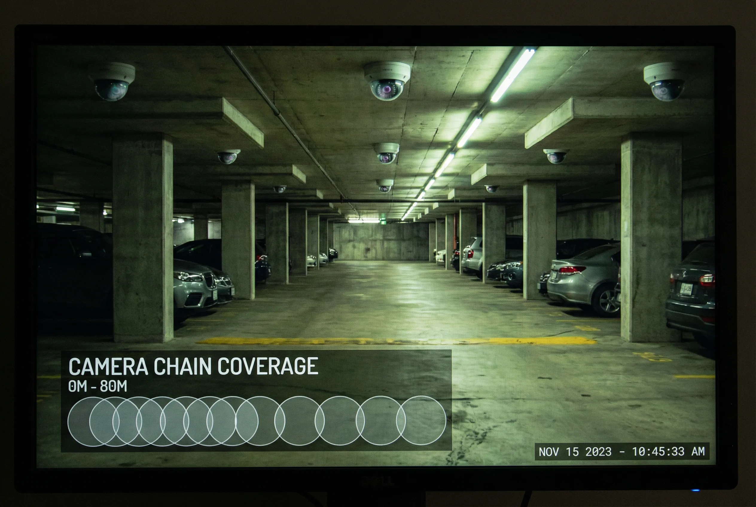
Ramps combine curvature, gradient, and confined walls — a combination that creates the highest collision risk zone in underground parking facilities. Accidents occur most frequently at the apex of the curve where drivers cannot see oncoming vehicles or pedestrians approaching from the other direction. Illumination levels are typically worst on ramps due to fixture spacing constraints and shadows cast by structural beams and walls.
A single camera cannot provide adequate coverage of both the ramp entry and the apex. The proven approach is a chained camera deployment: one camera covering the ramp entry zone, one at the apex with a wide-angle lens, and one at the ramp exit, with deliberate overlapping fields of view between adjacent cameras. This chain ensures that any vehicle can be visually traced continuously from entry to exit, which is essential for proving speed and lane position in accident investigations.
Evidence from ramp incidents requires multi-camera synchronized playback with accurate timestamps. NTP time synchronization is therefore non-negotiable on ramp cameras. Vibration from passing vehicles can cause camera misalignment over time, requiring periodic angle verification as part of the O&M routine.
Key Demands & Constraints
- Ramp curvature limiting single-camera coverage
- Vibration from vehicles affecting alignment
- Low lux levels due to fixture spacing
- Headlight reflection off concrete walls
- Limited mounting height on low ceiling
- Dust and exhaust particle accumulation
- Lens fogging from temperature differentials
- Cable routing constraints along ramp walls
Key Technical Indicators
- No blind zone >3 m along ramp
- Vehicle trace continuity across 3 cameras
- Motion blur acceptable at 15 km/h
- Frame rate: ≥25 fps
- WDR: ≥120 dB
- IP rating: IP66, IK10
- NTP offset: <500 ms
- Synchronized multi-camera replay: pass
Cross Intersection with Multi-Direction Traffic
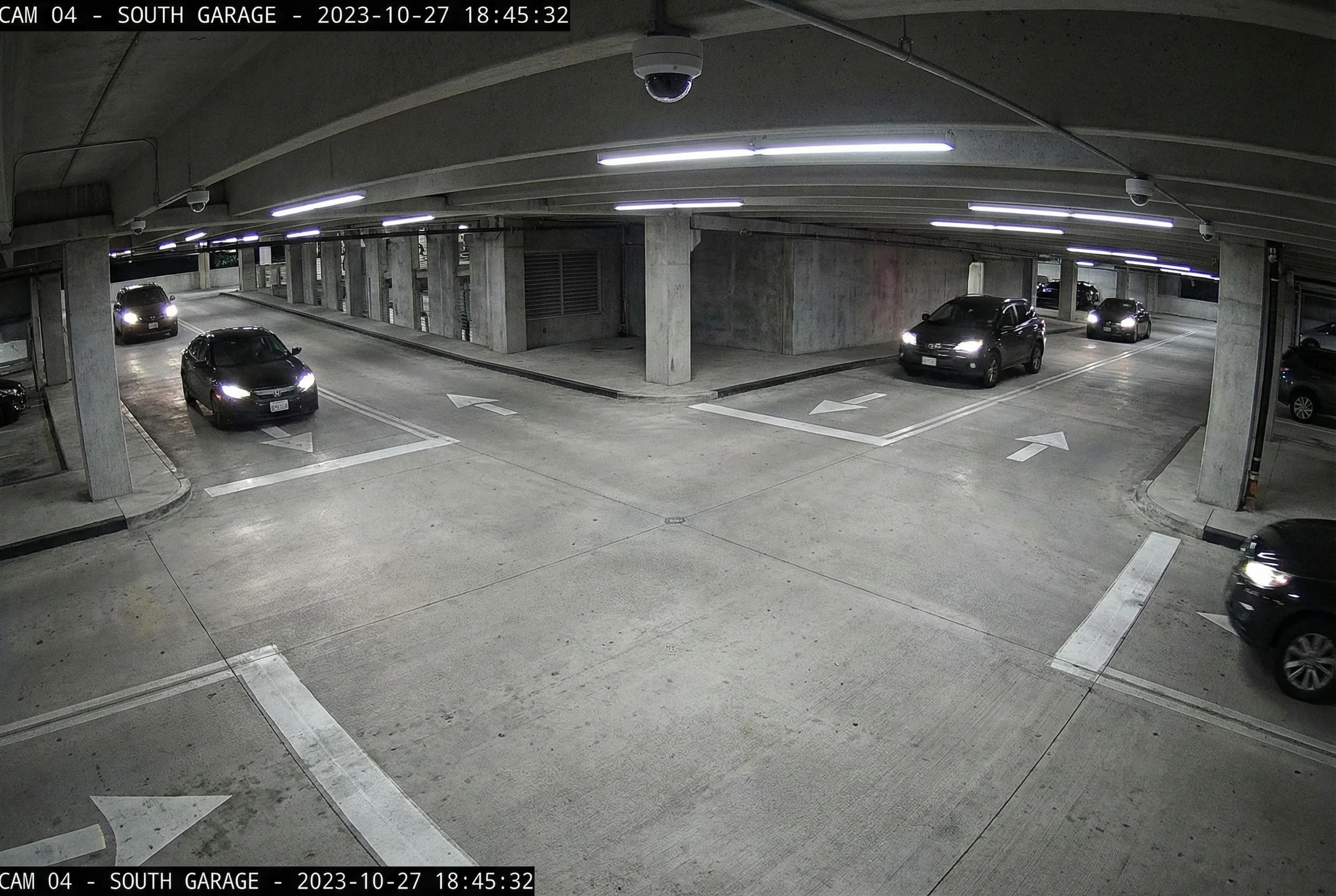
Underground intersections — whether 3-way or 4-way — are high-risk zones where vehicles approach from multiple directions with limited mutual visibility due to parked cars and structural columns blocking sight lines. Drivers frequently violate stop rules at these intersections. Forensic evidence must clearly show which vehicle entered the intersection first and from which lane, requiring both contextual overview and directional detail simultaneously.
A panoramic multi-sensor camera mounted at the ceiling center provides the necessary situational context, but its pixel density at the intersection perimeter may be insufficient for vehicle identification. The recommended configuration pairs the panoramic camera with dedicated directional cameras targeting each approach lane, creating a two-tier evidence system: context from the panoramic and detail from the directional cameras.
Optional AI analytics such as wrong-way vehicle detection can reduce incident frequency, but must be carefully tuned to avoid false alarms caused by shadows, reflections, and legitimate U-turns. Alarm fatigue from excessive false positives is a significant operational risk that must be addressed during commissioning.
Key Demands & Constraints
- Column occlusion at intersection corners
- Multiple approach directions simultaneously
- Mixed vehicle speeds and types
- Low contrast in overhead lighting
- Need for both context and detail coverage
- Limited ceiling cabinet space for equipment
- Cross-camera correlation for sequence proof
- Alarm fatigue risk from analytics
Key Technical Indicators
- Full intersection coverage: 360° panoramic
- Identifiable vehicle types at all approaches
- Clear direction of travel in footage
- Multi-sensor resolution: 8–12 MP
- False alarm rate: <5% with analytics
- Replay shows entry sequence unambiguously
- WDR: ≥120 dB per sensor
- Frame rate: ≥20 fps
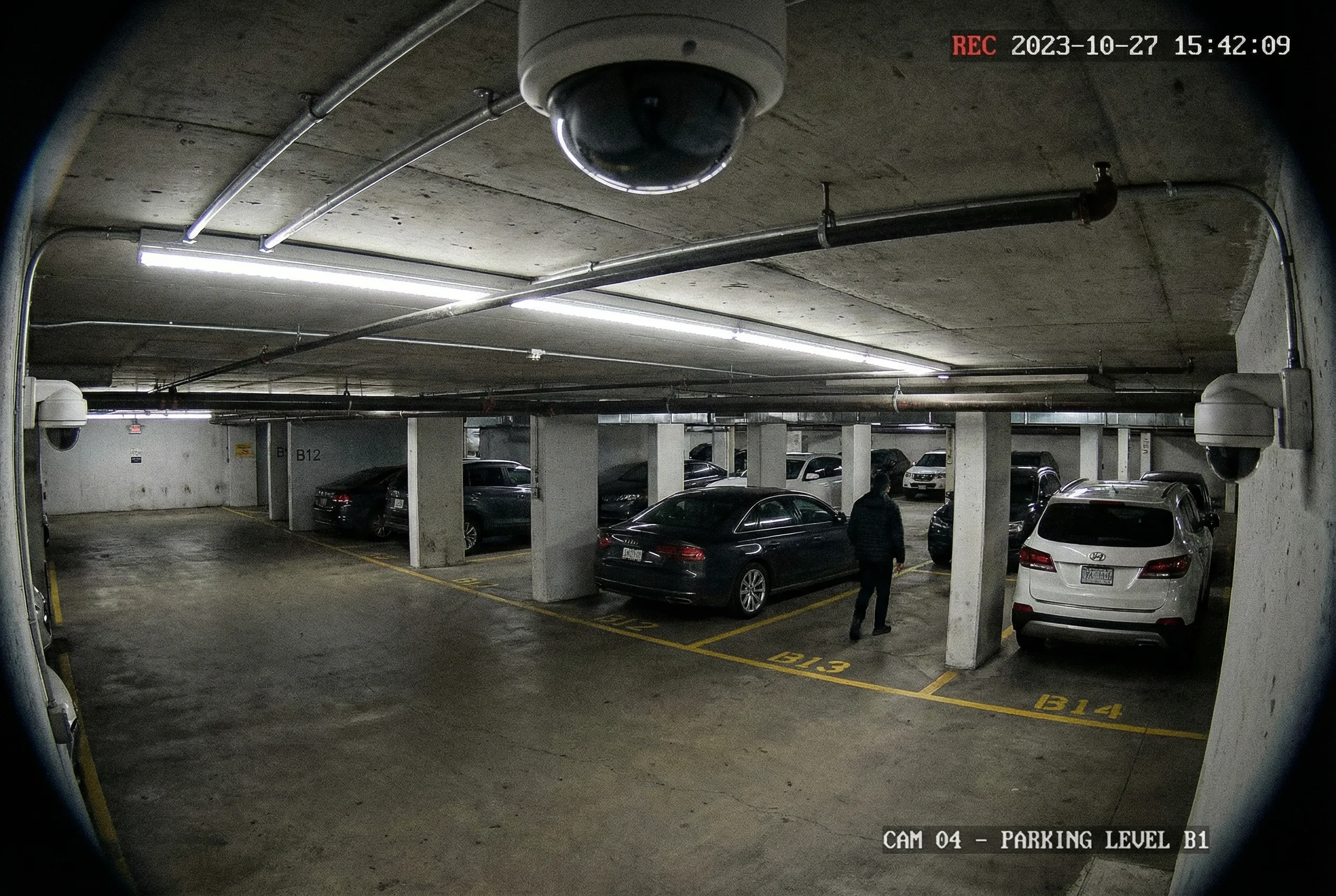
Long Drive Aisle with Repeating Columns and Parked Vehicles
Drive aisles are the most spatially repetitive zones in underground parking facilities — long, uniform corridors with predictable occlusion patterns created by structural columns at regular intervals and parked vehicles on both sides. The most common design error in aisle coverage is spacing cameras too far apart, leaving unobserved segments hidden behind columns that create forensic blind spots where theft, vandalism, or pedestrian incidents go unrecorded.
The correct approach uses moderate focal lengths (2.8–4 mm for typical 6–8 m wide aisles) with staggered mounting positions that ensure overlapping coverage at every column line. Mounting cameras on the ceiling between structural beams, rather than on columns, reduces glare from headlights and provides more consistent coverage angles. Continuous recording at an optimized bitrate is essential; event-based recording alone frequently misses key segments when motion detection fails to trigger on slow-moving or stationary threats.
Exhaust haze and dust accumulation on lens windows are significant maintenance concerns in high-traffic aisles. Cameras with self-cleaning lens coatings or scheduled cleaning protocols should be specified. Consistent camera naming (floor-zone-sequence) enables fast clip retrieval during incident investigation.
Key Demands & Constraints
- Repeating column occlusions at regular intervals
- Limited cable tray capacity along aisles
- Low lux levels between fixture positions
- Exhaust haze reducing visibility
- Theft and vandalism risk to cameras
- Need for consistent naming and indexing
- Bandwidth minimization for long aisles
- Minimal maintenance access disruption
Key Technical Indicators
- No hidden column segment >2 m
- Person detection at ≥15 m distance
- Stable bitrate: ±10% of target
- Minimal glare hotspots from headlights
- Resolution: 4 MP per camera
- Frame rate: 20–25 fps
- IP rating: IP66, IK10
- Camera spacing: ≤12 m (typical)
Parking Bay Area for Vandalism and Vehicle Scratch Evidence
Parking bay disputes — door dings, key scratches, hit-and-run while parked — are among the most frequent and difficult-to-resolve incidents in underground facilities. Evidence must show the proximity and actions of a person or vehicle near the damaged car, requiring wide area coverage with sufficient pixel density to identify actions at the bay level. This is a challenging balance: wide coverage typically means lower pixel density per bay.
Multi-sensor panoramic cameras or fisheye cameras provide the necessary wide coverage, but pixel density must be validated at the design stage using the pixels-on-target calculation for the furthest bay in the coverage zone. High-dispute zones — near elevator lobbies, premium bays, and narrow end bays — benefit from additional fixed cameras providing targeted coverage. Privacy constraints may apply if the camera field of view extends beyond the facility boundary into adjacent private areas.
Storage volume is a key consideration for bay area cameras: wide-area cameras at high resolution generate significant bitrate. VBR encoding with ROI (region of interest) compression can substantially reduce storage requirements while maintaining evidence quality in the active areas of the frame.
Key Demands & Constraints
- Very wide field of view requirement
- Low lux levels between bay lighting fixtures
- High detail requirement for action identification
- Mounting height constraints (low ceiling)
- Privacy masking for boundary areas
- High storage volume from wide-area cameras
- Cleaning needs for fisheye lens surfaces
- Vandal-proof housing requirement
Key Technical Indicators
- Coverage per bay block: full visibility
- Person actions near cars: identifiable
- Resolution: 6–12 MP or fisheye
- Frame rate: 15–20 fps
- WDR: ≥120 dB
- Exportable evidence: hash-verified
- Low distortion at bay perimeter: validated
- Search time: <3 minutes for incident clip
Elevator Lobby / Stair Door for Personal Safety and Access Events
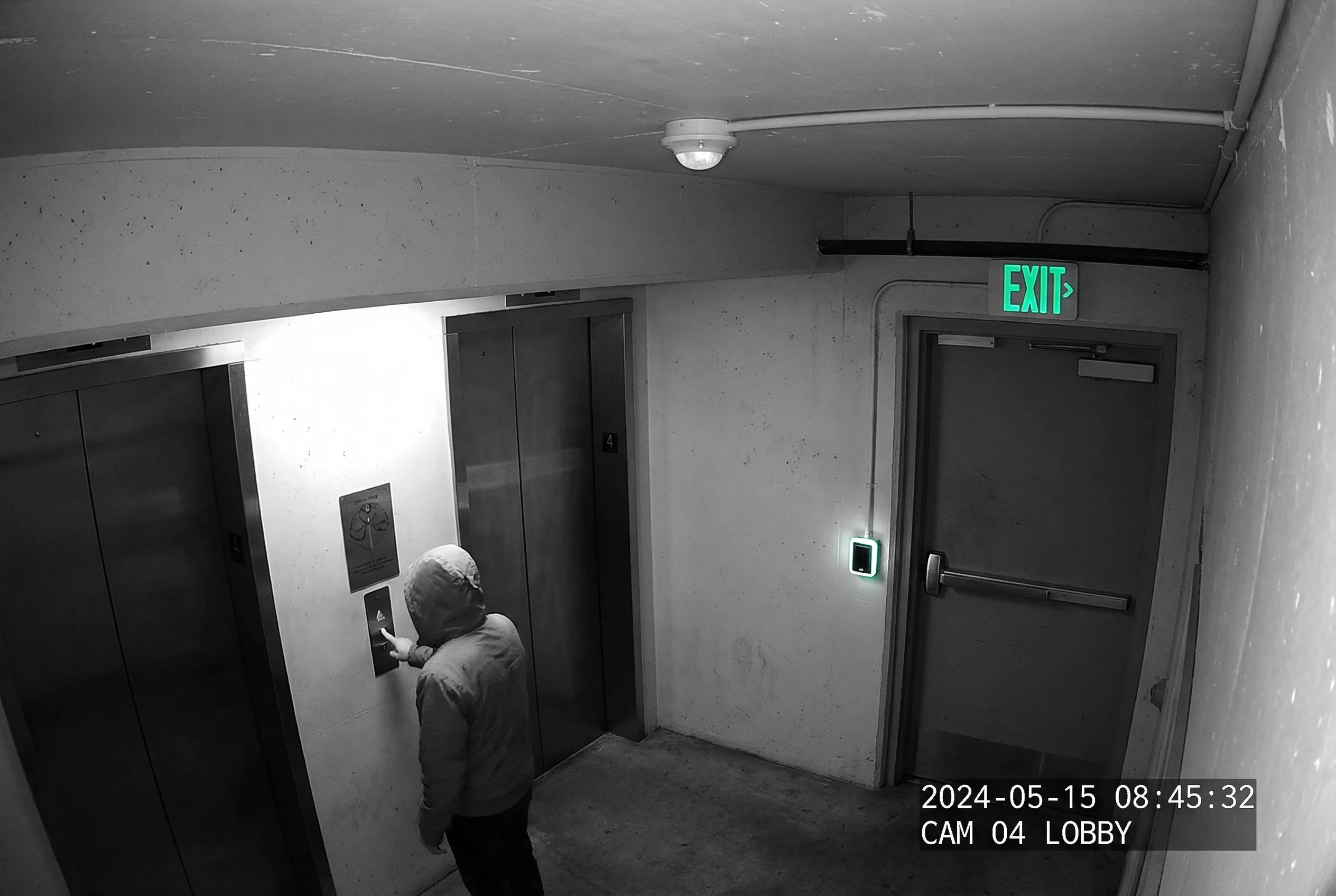
Elevator lobbies and stairwell doors are hotspots for personal safety incidents, unauthorized access attempts, and disputes involving building residents or visitors. These zones typically have better ambient lighting than drive aisles, but face a specific challenge: strong backlight from elevator doors opening and closing creates exposure problems that can make faces unidentifiable at the critical moment of entry or exit.
Camera placement must be optimized for face capture at the target identification distance, with the camera positioned to avoid direct backlight from elevator doors. Anti-backlight exposure compensation or WDR must be active. Integration with the access control system is essential: door forced open, door held open too long, and access denied events should all trigger camera pop-up and priority recording in the VMS, enabling rapid response to security incidents.
Privacy masking may be required by local policy if the camera field of view captures areas beyond the facility's jurisdiction. Vandal-resistant housings are mandatory in these high-traffic areas where cameras are within reach of pedestrians.
Key Demands & Constraints
- Face capture at target identification distance
- Backlight from elevator doors
- Privacy requirements for adjacent areas
- Vandal resistance (within pedestrian reach)
- 24/7 reliability requirement
- Integration with door sensors and access control
- Event-to-video linkage within 2 seconds
- Audit log completeness for compliance
Key Technical Indicators
- Face identifiable at target distance: pass
- Event pop-up within: <2 s
- Audit logs: complete and tamper-evident
- WDR: ≥120 dB (anti-elevator backlight)
- Resolution: 4 MP
- IP rating: IP66, IK10
- Vandal failure rate: <1% annually
- Access event correlation: 100%
Payment / Guard Booth with Dispute Handling
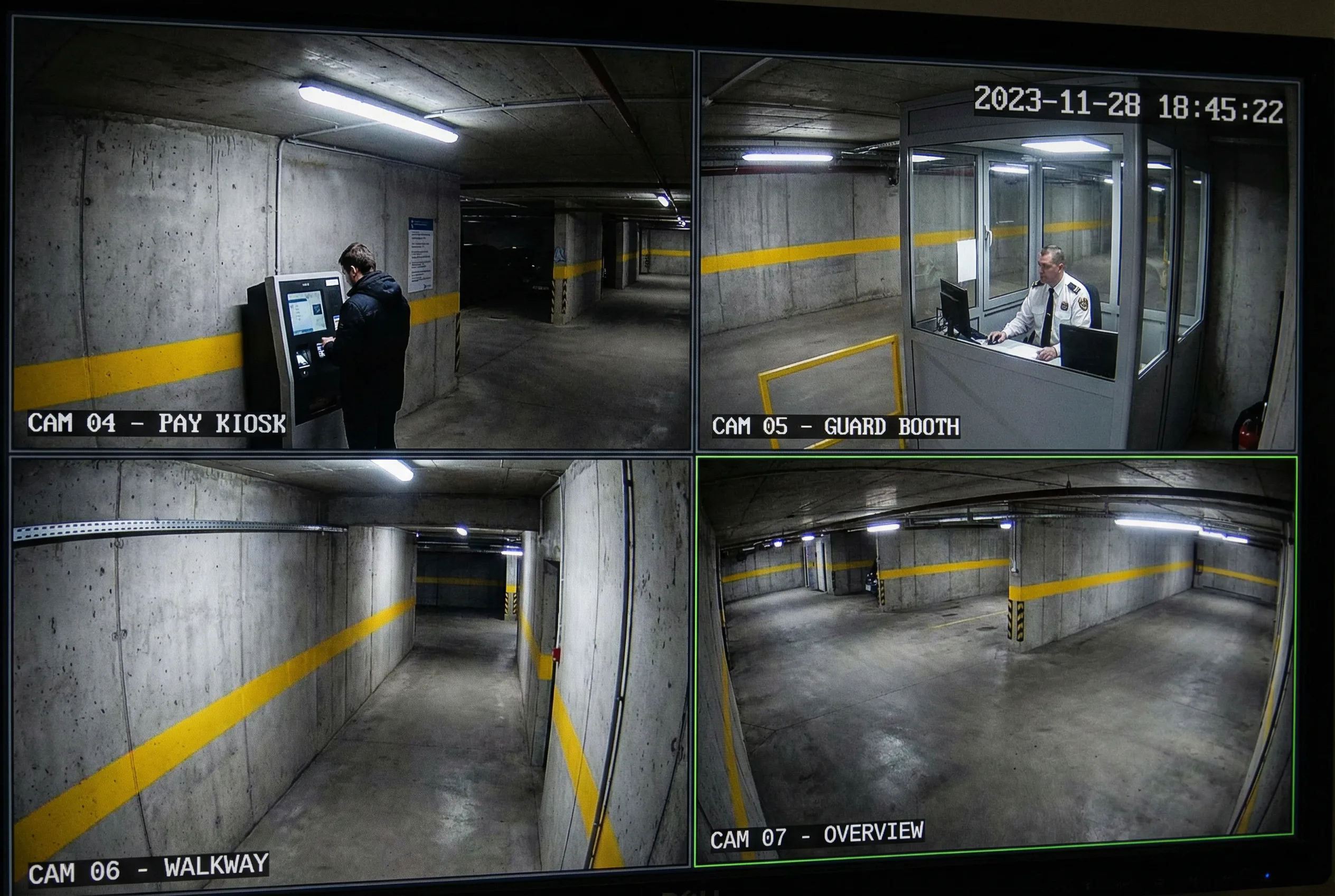
Payment booth and guard station areas require clear evidence of both the transaction interaction and the surrounding vehicle lane context. Disputes at payment kiosks and manned booths frequently involve claims of incorrect charges, cash handling disputes, or verbal altercations. Evidence must clearly show the driver's face, the payment terminal display, and the vehicle present at the time of the transaction.
The recommended configuration uses two cameras: a close-up camera with controlled exposure targeting the transaction area and driver window, and an overview camera providing lane context and vehicle identification. Lighting in booth areas is typically mixed — monitor glare from the payment terminal, exterior headlights, and interior booth lighting create a challenging multi-source lighting environment that requires careful exposure management.
Transaction timestamp correlation is critical for dispute resolution: the VMS must be able to retrieve footage by transaction ID or time, and the parking billing system must log timestamps that align with the video timeline. Extended retention (90–180 days) is often required for financial dispute resolution under local regulations.
Key Demands & Constraints
- Mixed lighting: monitor glare + headlights
- Reflections from booth glass and surfaces
- Audio recording compliance requirements
- Transaction timestamp linkage
- Operator usability for quick retrieval
- Secure storage for financial evidence
- Redundancy for critical transaction evidence
- Limited camera mounting space in booth area
Key Technical Indicators
- Clear transaction view: driver face + terminal
- Time correlation with billing logs: <1 s
- Quick retrieval: <3 minutes
- Retention: 90–180 days (financial)
- WDR: ≥120 dB (mixed lighting)
- Resolution: 4 MP (close-up)
- Evidence export: hash-verified
- Uptime: >99.5% monthly
Equipment Room / Electrical Room Intrusion and Safety Monitoring

Equipment rooms and electrical distribution rooms are critical infrastructure spaces that are high-value targets for unauthorized entry. These rooms house the surveillance system's own servers, network switches, UPS units, and electrical distribution panels — meaning a security failure here can compromise the entire surveillance system. Cameras in these rooms must maintain reliable operation under electromagnetic interference (EMI) from electrical equipment and must handle low-light conditions typical of utility spaces.
Integration with intrusion detection sensors and cabinet environment sensors is essential. Door open events, temperature threshold breaches, and humidity alarms should all trigger camera pop-up and priority recording. Cybersecurity controls for equipment room cameras must be particularly strict because these networks may be adjacent to building operational technology (OT) systems, and a compromise here could affect building-wide systems.
Maintenance windows for equipment room cameras must be carefully planned to avoid creating surveillance gaps during system updates or hardware replacement. A documented maintenance procedure with a temporary coverage plan is required for any camera that must be taken offline.
Key Demands & Constraints
- EMI from electrical equipment
- Restricted access (authorized personnel only)
- High reliability requirement (24/7)
- Low light in utility space
- Environmental alarms integration
- Integration with door sensors
- Strict cybersecurity (adjacent to OT systems)
- Planned maintenance windows
Key Technical Indicators
- Intrusion events: 100% recorded
- Alarms delivered: <15 s from trigger
- No EMI-induced stream drops
- Auditability: complete access log
- Low-light sensitivity: ≤0.01 lux (color)
- IP rating: IP66
- Uptime: >99.9% (critical infrastructure)
- Cybersecurity checklist: pass
3.3 Scenario → Solution Mapping Matrix
The following matrix maps each scenario to its recommended camera type, optics strategy, lighting approach, recording configuration, and key integration requirements. This matrix serves as a rapid selection reference during the design phase and should be cross-referenced with the quantitative metric ranges in Section 3.6 to validate final specifications.
| Scenario | Primary Camera Type | Optics Strategy | Lighting Strategy | Recording Strategy | Key Integration |
|---|---|---|---|---|---|
| A: Entrance/Exit | Dedicated LPR + overview dome | Longer focal, narrow ROI | IR/white controlled, anti-glare placement | Event + continuous dual-stream | Gate/billing system |
| B: Ramp | Fixed cameras chain (3 per ramp) | Medium focal, overlap at apex | WDR tuning, low-light SNR | Continuous high priority | Incident workflow |
| C: Intersection | Panoramic multi-sensor + directional | Wide + medium focal combination | WDR per sensor | Continuous + event bookmarks | Optional AI analytics |
| D: Drive Aisle | Fixed turret/bullet, staggered | Medium focal, overlap at columns | Low-light + WDR | Continuous optimized bitrate | Patrol operations |
| E: Parking Bays | Fisheye/multi-sensor + hotspot fixed | Very wide + fixed at disputes zones | Low-light, ROI encoding | Continuous optimized | Optional occupancy sensors |
| F: Lobby/Stair | Vandal dome, face-angle optimized | Face capture optimized focal | WDR, anti-elevator backlight | Event priority on access events | Access control system |
| G: Booth | Close-up + overview (2 cameras) | Mixed focal: close-up + wide | Controlled interior lighting | Extended retention (90–180 days) | Transaction logs, billing |
| H: Equipment Room | Fixed + environmental monitoring | Medium focal, full room coverage | Low-light, IR | Event + continuous | Intrusion sensors, fire alarm |
3.6 Recommended Metric Ranges by Zone
The following table provides the recommended technical specification ranges for each zone type. These values represent engineering targets derived from real-world deployment experience and should be used as minimum baselines during camera selection and system design. Site-specific conditions may require adjustments — particularly for WDR requirements at portals with unusually strong backlight, or frame rate requirements at entrances with high vehicle throughput.
| Zone | Resolution | FPS | WDR | Target Shutter | Plate Pixels | Notes |
|---|---|---|---|---|---|---|
| Entrance LPR | 2–4 MP | 25–50 | ≥120 dB | 1/500–1/2000 s | ≥140 px | Controlled exposure; dedicated LPR camera |
| Ramp | 4 MP | 25 | ≥120 dB | 1/250–1/1000 s | N/A | Overlap required; 3 cameras per ramp |
| Intersection | 8–12 MP (multi-sensor) | 20–25 | ≥120 dB | Adaptive | Optional | Context + detail; panoramic + directional pair |
| Drive Aisle | 4 MP | 20–25 | ≥120 dB | Adaptive | Optional | Low-light tuning; staggered mounting |
| Parking Bay | 6–12 MP or fisheye | 15–20 | ≥120 dB | Adaptive | Optional | Validate pixel density at bay perimeter |
| Lobby / Stair | 4 MP | 20–25 | ≥120 dB | 1/100–1/500 s | N/A | Face capture angle; anti-elevator backlight |
| Payment Booth | 4 MP (close-up) | 25 | ≥120 dB | Adaptive | N/A | Two-camera setup; extended retention |
| Equipment Room | 4 MP | 20 | ≥100 dB | Adaptive | N/A | Low-light; EMI-resistant; event-triggered |