Chapter 4: Architecture Design
Typical system topology, core performance indicators, device wiring, and business logic flows
4.1 Typical System Topology
The typical underground parking surveillance system topology is organized as a five-layer hierarchy, with clearly defined data flows, redundancy paths, and power dependencies at each layer. The design prioritizes recording continuity and evidence integrity as the primary non-negotiable requirements, with all redundancy decisions made to protect these outcomes.
At the field layer, cameras are grouped into functional zones — entrance/exit, ramps, aisles, intersections, bay areas, lobbies, booths, and equipment rooms. Each zone connects to a dedicated PoE access switch housed in a local distribution cabinet. Access switches uplink via dual fiber paths to floor-level distribution switches, which connect via independent fiber routes to a dual-stack core switch in the main equipment room. This dual-path fiber design ensures that a single cable cut or switch failure cannot isolate an entire floor's cameras from the recording platform.

Figure 4.1: Typical System Topology — Five-Layer Architecture with Redundant Uplinks, HA Platform, and UPS Power Paths
Redundancy Design Principles
- Dual uplinks: Every access switch has two fiber uplinks to the distribution switch via physically separate cable routes (different conduit paths)
- Core redundancy: Core switches are deployed as a stack or MLAG pair with dual power supplies; failover time <50ms
- Recording redundancy: Either N+1 NVR configuration or VMS HA pair with shared storage; cameras automatically rebind to standby node on primary failure
- UPS coverage: Core switch, storage array, and entrance switches/cameras are all on UPS-backed circuits; minimum 30-minute runtime for core, 15 minutes for edge
- Time synchronization: Dual NTP sources with monitoring; all devices must maintain offset <500ms from NTP server
| Layer | Key Nodes | Uplink Spec | Redundancy Method | UPS Required |
|---|---|---|---|---|
| Field (Cameras) | LPR, dome, fisheye, panoramic | Cat6 PoE 802.3at/bt | Dual power feed to switch | Via switch UPS |
| Access (PoE Switches) | 24/48-port managed PoE | 10G fiber, LACP | Dual fiber uplinks (A/B) | Yes (entrance zones) |
| Distribution | L3 floor switches | 10G fiber to core | Dual-homed to core MLAG | Yes |
| Core | MLAG/stack core switch | 10G/25G to platform | MLAG, dual PSU | Yes (critical) |
| Platform | VMS HA pair, storage RAID | 10G iSCSI/NFS | HA active/standby, RAID6/10 | Yes (critical) |
4.2 Core Functions and Performance Indicators
The following table defines the twelve core performance indicators for the surveillance system, each with its operational impact, implementation path, and acceptance verification method. These indicators form the basis of the acceptance test plan and should be measured during both commissioning and periodic O&M audits. Failure to meet any indicator in the "Critical" category constitutes a system defect that must be resolved before handover.
| Indicator | Priority | Impact | Implementation Path | Acceptance Method |
|---|---|---|---|---|
| Recording Continuity | Critical | Evidence integrity — gaps invalidate forensic value | Bandwidth + storage sizing; RAID; HA failover | 72-hour no-gap recording test; playback verification |
| Plate Read Rate | Critical | Billing and dispute resolution accuracy | LPR optics + exposure tuning; controlled illuminator | Day/night drive-through test; 50+ plate samples |
| Time Offset | Critical | Cross-camera replay accuracy for incident reconstruction | NTP mandatory on all devices; monitoring alerts | Offset audit: all devices <500ms from NTP |
| Playback Search Time | High | Operational efficiency; incident response speed | Zone naming standard; event/plate indexing; bookmarks | Retrieve target clip within 3 minutes from incident time |
| Stream Stability | Critical | Recording gaps from packet loss or congestion | QoS marking; link budget; storm control; LACP | Packet loss <0.01%; bitrate variance <±10% |
| WDR Performance | Critical | Plate/face readability under headlights and backlight | WDR sensor ≥120dB; tuned exposure profiles per zone | Headlight/backlight test at portal; plate readable |
| Low-Light Clarity | High | Identify persons and vehicle actions in dark zones | Low-light SNR; IR/white illuminator strategy | Lux-based test at minimum illumination level |
| Storage Retention | Critical | Compliance with retention policy; legal evidence availability | Capacity planning; tiered retention; VBR+ROI | Verify days stored; no premature overwrite |
| HA Failover Time | High | System uptime during server or network failure | VMS HA cluster; camera rebind to standby NVR | Simulated failover test; recording gap <30s |
| Cyber Hardening | Critical | Prevent unauthorized access and evidence tampering | VLAN/ACL; MFA; signed firmware; syslog; no default creds | Security checklist pass; penetration test baseline |
| Environmental Resilience | High | Reduce hardware failures from moisture and temperature | IP66/67 ratings; sealed glands; RH monitoring; drip loops | Water drip simulation; RH alarm threshold test |
| Maintenance MTTR | Medium | Faster fault recovery; lower operational cost | Consistent labeling; cable slack; spare parts inventory | Timed camera replacement drill; <2 hours for LPR swap |
4.3 Device Connection Diagram
The device connection diagram illustrates the physical wiring path from each camera through the structured cabling system to the platform layer, including all intermediate components, connection types, and grounding requirements. Every connection in this path has a specific requirement that, if not met, creates a predictable failure mode — from water ingress at unsealed glands to recording gaps from undersized fiber uplinks.
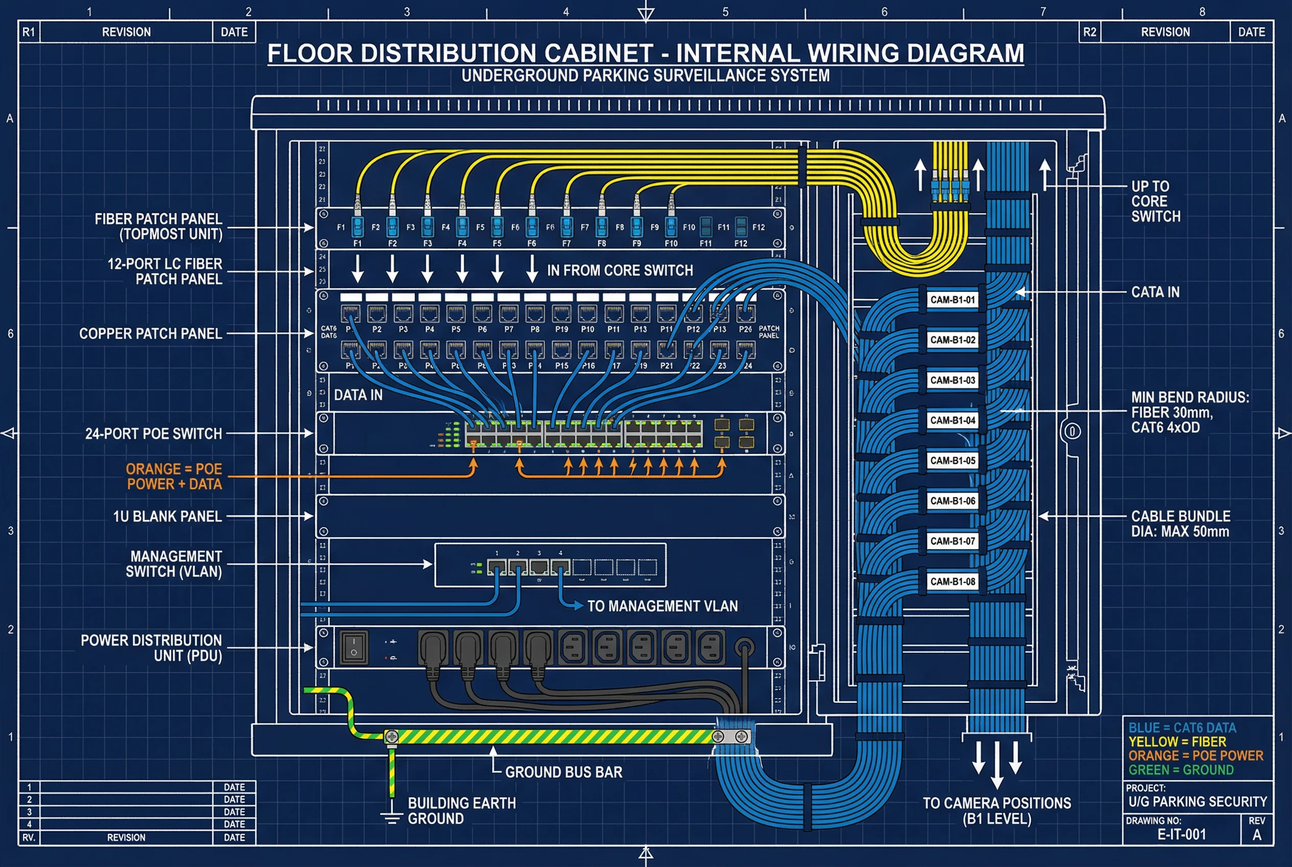
Figure 4.2: Device Connection and Wiring Diagram — Camera to Platform Path with Grounding, UPS, and Integration Interfaces
Critical Wiring Requirements
- Drip loop: All camera cable entries must form a downward drip loop before entering the waterproof junction box to prevent water from running into the housing along the cable
- IP67 glands: Cable glands must match the cable outer diameter (OD) precisely; oversized glands allow moisture ingress even with IP67-rated housings
- Conduit fill: Metal conduit preferred in underground environments; fill ratio <40% to allow future cable additions and heat dissipation
- Fiber routing: Dual fiber uplinks (A/B paths) must be routed through physically separate conduits and cable trays to prevent a single incident from cutting both paths
- Grounding: All equipment cabinets must be bonded to the building equipotential grounding bus; ground resistance <4Ω; surge protection devices (SPD) installed at all outdoor cable entries
- Cable length: Cat6 copper runs must not exceed 90m (structured cabling) + 10m patch cords; longer runs require fiber media converters
4.4 Business Logic and Exception Handling
The system's business logic defines the normal data and control flows, the switching and recovery behaviors during failures, and the exception handling chains for the three most critical failure scenarios. Understanding these flows is essential for both commissioning verification and O&M response planning.
Normal Operation Flows
- Data flow: Main stream recorded continuously; sub stream for live preview; metadata (plate events, motion, analytics) indexed in VMS database
- Control flow: Alarms trigger camera pop-up in VMS, PTZ preset moves (if applicable), and priority recording mode activation
- Evidence flow: Operators search by time/camera/zone/plate; export evidence package with cryptographic hash; hash recorded in audit log
| Exception | Trigger | System Behavior | Recovery Action | Prevention |
|---|---|---|---|---|
| Core Uplink Fiber Cut | Physical fiber damage or switch failure | LACP reroutes to secondary path; VMS raises critical alarm; recording continues on secondary path | Dispatch cable repair; verify recording continuity; document gap if any | Dual fiber paths in separate conduits; LACP bonding |
| Storage Volume Near Full | Disk utilization >85% of retention target | VMS enforces retention deletion policy; if deletion fails, blocks new writes and raises critical alarm | O&M expands storage capacity; review bitrate and retention settings; add disks | Capacity calculator with 20% headroom; SMART monitoring; VBR encoding |
| Fire Alarm Active | Fire panel dry contact or API signal | VMS enters fire mode: prioritizes evacuation route cameras, maintains recording at highest priority, sends linkage signals to gate and PA system | Follow fire safety protocol; do not shut down surveillance during evacuation; restore normal mode after all-clear | Pre-configured fire mode rules; tested annually; documented in O&M manual |