Chapter 5: Selection & Interfaces
Core product overview, function specifications, quantitative requirements, and interface design
5.1 Core Product Overview
The underground parking surveillance system is composed of five camera product families, three network device categories, three platform components, and a set of supporting infrastructure products. Each product family has defined key selection criteria and typical deployment positions that determine which product type is appropriate for each zone. Selecting the wrong product family for a zone — for example, using a general dome camera instead of a dedicated LPR camera at the entrance — creates a predictable evidence quality failure that cannot be corrected through configuration alone.

Figure 5.1: Core Product Family Overview — Camera Types, Network Devices, Platform Components, and Support Products with Key Selection Criteria and Deployment Positions
5.2 Core Product Functions
Each core product category has a defined set of functional capabilities that must be verified during procurement and commissioning. The following product cards list the minimum required functions for each product type. Functions marked as optional represent capabilities that are recommended for most deployments but may be omitted based on site-specific requirements and budget constraints.
5.3 Quantitative Requirements
The following table defines the minimum and recommended quantitative specifications for each critical system parameter, along with the engineering rationale and the consequence of specification mismatch. These values must be verified during procurement and confirmed during acceptance testing. Any specification below the minimum requirement constitutes a non-conformance that must be documented and resolved.
| Parameter | Minimum Requirement | Recommended | Engineering Rationale | Mismatch Consequence |
|---|---|---|---|---|
| WDR (Entrance) | ≥120 dB | ≥140 dB | Headlights and backlit exits create extreme contrast | Plate washout; billing disputes unresolvable |
| FPS (Entrance) | ≥25 fps | 50 fps | Higher FPS reduces motion blur probability | Missed frames; blurred plates at higher speeds |
| Shutter Range | To 1/2000 s | To 1/5000 s | Fast shutter freezes plate motion at 30 km/h | Motion blur; unreadable plates |
| PoE Budget per Switch | Ports × (avg W) | +30% margin | Prevents brownout during simultaneous camera startup | Reboot loops; recording gaps during power events |
| Uplink Capacity | ≥4× access sum / oversub ratio | 10G per floor | Prevents congestion during peak recording periods | Packet loss; recording gaps; evidence unusable |
| Storage Write Throughput | ≥1.2× total bitrate | ≥1.5× | RAID overhead and burst writes require headroom | Dropped frames; recording gaps under load |
| RAID Level | RAID5 minimum | RAID6/10 | RAID6 tolerates 2 simultaneous disk failures | Data loss on second disk failure during rebuild |
| Time Synchronization | NTP mandatory | NTP + monitoring | Multi-camera replay requires aligned timestamps | Timeline disputes; multi-camera replay unusable |
5.4 Connection and Interface Design
The interface design covers four classes of connections between system components: video streams, event data, physical I/O, and identity/time services. Each interface class has a defined protocol, direction, and compatibility requirement. The diagram below illustrates the typical wiring and interface logic from a camera through the network to the VMS platform, and from the VMS to all integrated external systems.
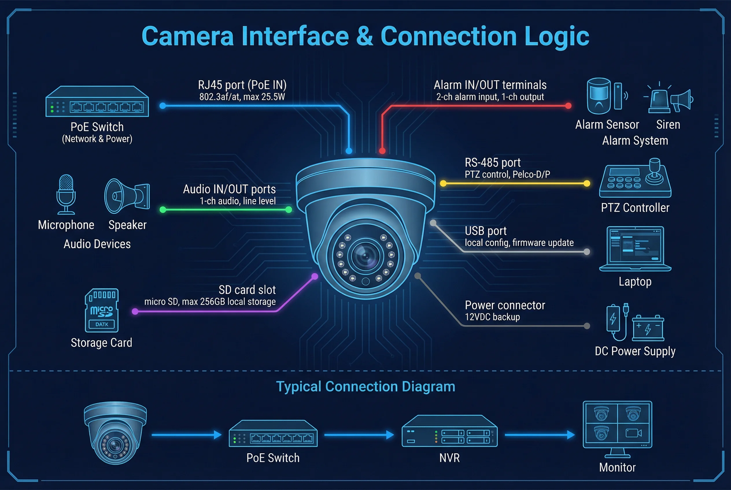
Figure 5.2: Typical Wiring and Interface Logic — Camera to VMS Platform with NTP, Gate, Fire Alarm, Access Control, and Billing System Interfaces
Interface Classes
| Interface Class | Protocol | Direction | Key Parameters |
|---|---|---|---|
| Video Stream | RTSP / ONVIF Profile S/T | Camera → VMS | H.265 main stream + sub stream; multicast optional |
| LPR Events | HTTP POST / SDK / MQTT | Camera/Engine → VMS | JSON payload: plate, confidence, lane, timestamp |
| Gate Control | Dry Contact / RS-485 | VMS → Gate Controller | Open/close pulse, 24V DC; relay output |
| Billing System | HTTPS REST API | VMS ↔ Billing | Plate + timestamp + lane ID; retry logic required |
| Fire Alarm | Dry Contact / API | Fire Panel → VMS | Zone ID; triggers fire mode in VMS |
| Access Control | SDK / OSDP / API | Access ↔ VMS | Door events: forced open, held open, access denied |
| Time Synchronization | NTPv4 | NTP Server → All Devices | Offset <500ms mandatory; monitoring alert on drift |
| Management / Monitoring | SNMP v3 / Syslog | All Devices → Monitor | SNMP traps; syslog to central server; health metrics |
Compatibility and Upgrade Strategy
- Prefer ONVIF conformance for camera discovery and basic control; use vendor SDK only for advanced LPR features that require proprietary APIs
- Maintain a stable IP address plan with reserved pools per zone; document MAC-to-location mapping in the network management system
- Camera replacement should not require VMS re-architecture: preserve ONVIF profiles, naming conventions, and use configuration templates for rapid deployment
- Plan firmware upgrade windows with rollback packages; store golden configuration files for all device types in a version-controlled repository