Chapter 7: Support & Integration
Infrastructure requirements, cross-system interfaces, physical wiring, and integration mechanisms
7.1 Support Requirements
The underground parking surveillance system depends on seven categories of supporting infrastructure, each of which must be designed, installed, and accepted independently before the surveillance system can be commissioned. A failure in any supporting infrastructure category creates a predictable failure mode in the surveillance system — from recording gaps caused by network congestion to evidence database corruption caused by abrupt UPS failure. The integrated support requirements diagram below shows all seven categories and their relationships to the central surveillance system.
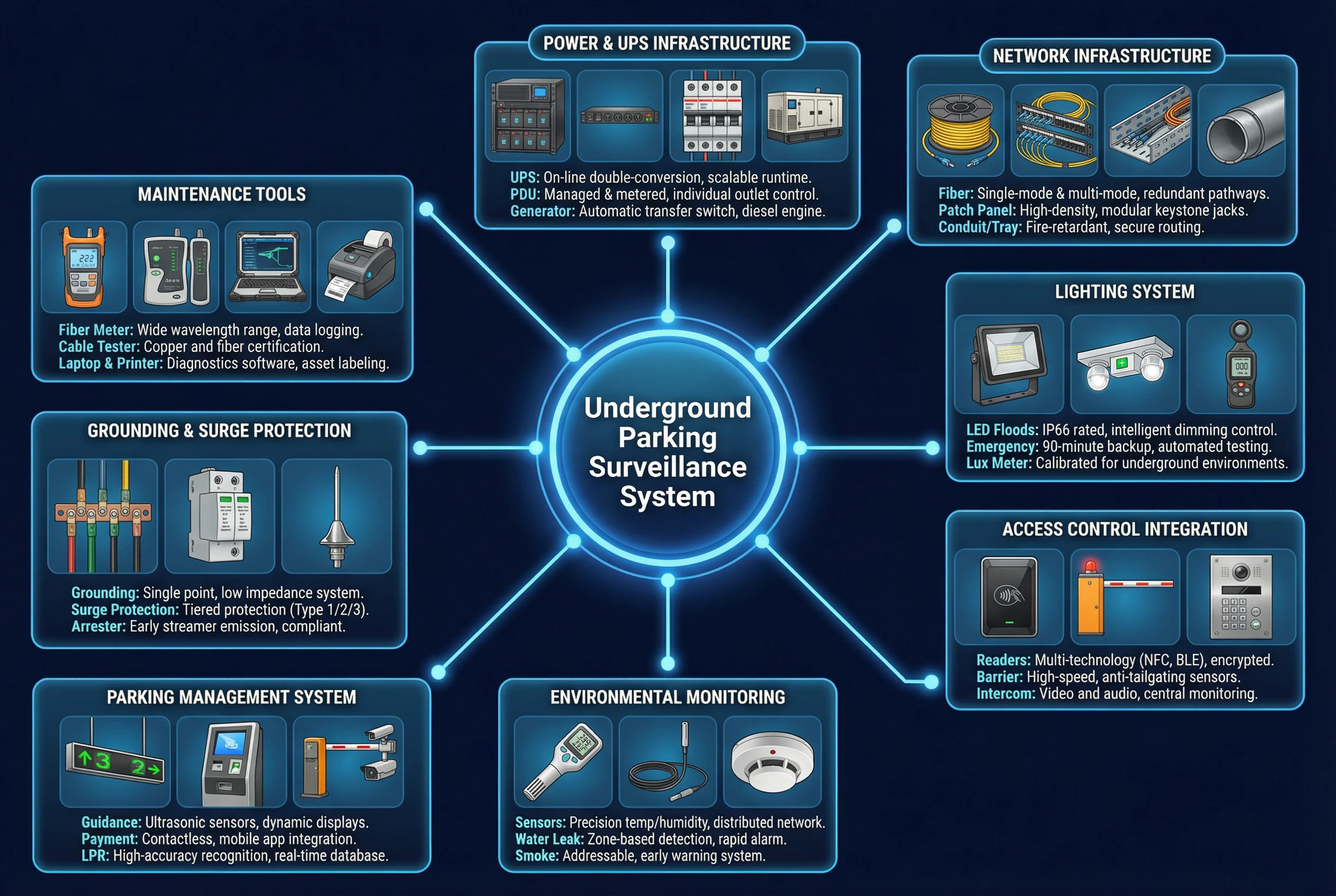
Figure 7.1: Integrated Support & Infrastructure Requirements — All Seven Supporting Categories with Key Specifications, Failure Risks, and Acceptance Criteria
| Support Category | Key Specification | Failure Risk | Acceptance Test |
|---|---|---|---|
| A. Communications & Network | 10G uplinks per floor; storm control; VLAN; QoS DSCP; labeled patch panel | Congestion → recording gaps; mislabeling → slow repair; no redundancy → single point of failure | Link redundancy failover test; packet loss <0.1% under full load; label audit |
| B. UPS | 30–60 min runtime for core+storage; 15–30 min for entrance switches; graceful shutdown script | Abrupt shutdown corrupts VMS database and evidence index; RAID rebuild interrupted | Power cut simulation; verify graceful shutdown sequence; runtime measurement |
| C. Power Distribution | Dedicated CCTV circuits; RCD on each circuit; thermal margin ≥20%; separation from high-noise loads | Shared circuit trip causes multi-camera outage; noise interference on PoE | Insulation resistance test; breaker coordination check; load test |
| D. Lightning & Grounding | Equipotential bonding; earth resistance <4Ω; SPD at all outdoor entries; numbered grounding points | Surge damages PoE switch ports and camera electronics; fiber preferred for long outdoor runs | Grounding continuity test; resistance measurement; SPD inspection record |
| E. Equipment Room | Temp 18–24°C; RH 40–60%; precision AC; access control; fire suppression; cable management | Overheating → disk failure; dust → fan clog; unauthorized access → evidence tampering | Thermal scan under full load; access control test; fire suppression inspection |
| F. Fire Alarm Linkage | Dry contact I/O gateway; fire mode policy in VMS; evacuation camera priority; PA integration | Wrong linkage causes confusion during evacuation; unsafe gate actions during fire | Joint fire drill test; verify VMS enters fire mode; confirm no unsafe gate actions |
| G. Physical Security Products | IK10 housings; anti-tamper screws; metal conduit; locked cabinets; tamper alarms | Vandalism disables key camera; cable damage creates recording gap; unauthorized cabinet access | Tamper alarm test; physical pull test; IK10 certification check |
7.2 Cross-System Interfaces & Integration
The surveillance system integrates with six categories of external systems, each requiring a defined interface protocol, data exchange format, and integration validation test. Integration failures are among the most common causes of operational problems in deployed systems — particularly the billing system interface, where retry logic and idempotency are critical to prevent duplicate billing events or missed transactions. Each interface must be tested end-to-end during commissioning, not just at the API level.
| External System | Interface Protocol | Data Exchanged | Direction | Critical Notes |
|---|---|---|---|---|
| Barrier Gate / Billing | HTTPS REST API / SDK | Plate number, timestamp, lane ID, snapshot URL | VMS → Parking System | Retry logic required; idempotency key to prevent duplicate billing |
| Access Control | Event API / Dry Contact I/O | Door forced open, door held open, access denied | Access Control → VMS | Triggers camera pop-up and priority recording in VMS |
| Fire Alarm System | Dry Contact / I/O Gateway | Fire zone ID, alarm state (active/clear) | Fire Panel → VMS | Triggers fire mode policy; must not cause unsafe gate actions |
| Intercom / Booth | SIP / SDK | Call event, audio (where legally permitted) | Booth ↔ VMS | Audio recording requires legal compliance review per jurisdiction |
| O&M Platform | SNMP v3 / Syslog / REST API | Device alarms, health metrics, configuration changes | VMS/Network → O&M | Auto-create maintenance tickets; alert on critical alarms |
| Parking Guidance | REST API | Bay occupancy status, zone availability | VMS/AI Engine → Guidance | Optional; requires AI analytics on camera feeds for bay detection |
7.3 Supporting Systems Mechanisms
Each supporting system has a defined operating mechanism, key performance indicators (KPIs) for ongoing monitoring, a maintenance schedule, and a documented failure impact chain that describes how a failure propagates through the surveillance system. Understanding the failure impact chain is essential for prioritizing O&M resources — a network switch failure has a different urgency than a cabinet cooling fan failure, even though both are maintenance issues.
| Support System | Mechanism | Key KPIs | Maintenance Schedule | Failure Impact Chain |
|---|---|---|---|---|
| Network | Switching/routing with VLAN, QoS, LACP redundancy | Packet loss <0.01%; latency <5ms; link uptime 99.9% | Monthly port audit; quarterly firmware review | Congestion → packet loss → recording gaps → evidence weak or invalid |
| UPS | Battery + inverter with automatic transfer switch | Battery runtime ≥30 min; battery health >80%; transfer time <20ms | Monthly runtime test; annual battery replacement cycle | Abrupt shutdown → VMS DB corruption → recording index lost → evidence unrecoverable |
| Grounding / SPD | Surge diversion to equipotential ground bus | Earth resistance <4Ω; SPD status indicator green | Annual resistance test; SPD visual inspection after storms | Surge event → PoE port damage → camera offline → recording gap at entrance |
| Equipment Room Cooling | Precision AC with redundant unit; thermostat-controlled fans | Inlet temp <35°C; RH 40–60%; alarm at 40°C | Monthly filter cleaning; quarterly AC service | Overheating → disk failure → RAID degraded → storage capacity reduced → retention shortened |
7.4 Physical Interface List
The physical interface list documents every physical connection point in the system, its connector type, typical installation location, and the most common installation error at that interface. These installation errors are documented because they are the most frequent causes of field failures — not equipment defects. Each error has a predictable consequence that can be avoided through proper installation practice and acceptance testing.
| Interface | Connector / Medium | Typical Location | Common Installation Error | Consequence |
|---|---|---|---|---|
| Camera Ethernet / PoE | RJ45, Cat6 UTP | Camera waterproof junction box | No waterproof boot or gland; no drip loop formed | Moisture ingress → connector corrosion → intermittent link drop → recording gaps |
| Fiber Uplink | LC duplex, OS2 SM | Floor distribution cabinet | Fiber A and B paths routed through same conduit | Single cable cut disables both redundant paths → floor-level recording outage |
| Fire Alarm I/O Signal | Dry contact, 2-wire | Fire alarm panel to I/O gateway | No isolation module between fire panel and I/O gateway | Voltage difference causes false triggers; fire panel may be damaged |
| Equipment Grounding | 6mm² earth strap, ring lug | Cabinet base to grounding bus | Loose ring lug; paint not removed from contact surface | High impedance ground path → surge damage to PoE ports and cameras |
| Power Feed to Cabinet | AC mains, 3-core cable | Distribution cabinet / UPS input | Shared circuit with HVAC or other high-noise loads | Circuit trip causes simultaneous outage of all cameras on that circuit |